インタラクティブデモ
30秒以下で検査フロー全体をご覧ください。
実際のスティック溶接の写真をFlaggity AIで分析し、AWS D1.1:2025およびISO 5817に対して検証します。サインアップ不要、カード不要、メール不要。本格導入のご準備ができたら、サインアップして自社の画像をアップロードしてください。
4枚の溶接写真を分析いたします
圧力容器の実際のフィレット溶接画像で、現場でスマートフォンにて撮影したものです。
Flaggity AIがすべての欠陥を引用いたします
気孔、アンダーカット、亀裂など、各々ISO 5817 / AWS D1.1条項に正確にマッピングされております。
完全なレポートをご確認いただけます
判定、重大度別の所見、是正処置、および監査対応済みPDFのプレビューをご覧いただけます。
Analyzing weld geometry…
Flaggity AI is inspecting every frame. Usually takes under 30 seconds.
デモ結果 · 読み取り専用
WELD 検査 · DEMO-001
Bay 3 — Tank Assembly Line · Demo Inspector(CWI-DEMO)により検査済み
AI サマリー
All four weld samples exhibit multiple critical and major defects that result in rejection across all ISO 5817 quality levels (B, C, and D). Critical defects include excessive undercut (Image 2) and incomplete fusion/cold lap (Image 3) that violate AWS D1.1:2025 structural requirements. Major defects include irregular weld profiles, excessive reinforcement, and porosity exceeding acceptable limits. Minor defects include excessive spatter requiring removal. Primary root causes appear to be improper welding parameters, inadequate welder technique, poor joint preparation, and insufficient shielding gas coverage. All welds require repair or complete removal and re-welding with improved process controls and welder training before acceptance.
指摘事項総数
7
重大
2
分析済み写真
4
検査写真
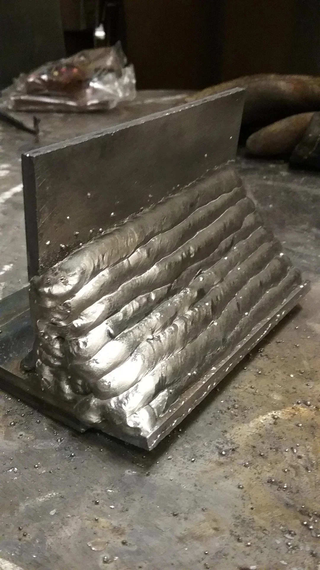
Excessive undercut
AWS D1.1:2025 · Clause 6.9.3.3 - Undercut limitations
是正措置: Repair immediately by grinding to smooth transition and re-welding affected areas. Reduce travel speed, adjust electrode angle, and optimize heat input to prevent undercut recurrence.
場所: Image 2: Severe undercut visible along multiple weld toes on multi-pass fillet weld, exceeding 1mm depth
Incomplete fusion / Cold lap
AWS D1.1:2025 · Clause 6.9.4 - Incomplete fusion
是正措置: Remove affected weld completely by grinding or gouging and re-weld. Increase heat input, reduce travel speed, and ensure proper electrode manipulation to achieve complete sidewall fusion.
場所: Image 3: Visible lack of fusion along weld toe showing distinct boundary line between weld metal and base metal
Irregular weld profile / Poor weld appearance
ISO 5817 · Table 1, Section 5.2 - Weld profile and reinforcement
是正措置: Grind and re-weld. Improve welder technique including travel speed, weave pattern, and heat input control. Ensure proper joint fit-up and cleaning.
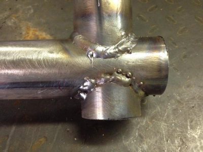
場所: Image 1: Pipe tee joint shows uneven, rough weld bead with poor tie-in and inconsistent profile around entire circumference
Excessive reinforcement / Overfill
ISO 5817 · Table 1, Section 5.2.2 - Excessive weld metal (h > limits)
是正措置: Grind excessive reinforcement to acceptable profile per ISO 5817 limits. Adjust welding parameters and reduce filler metal deposition rate.
場所: Image 2: Multiple passes show excessive convexity and buildup beyond acceptable reinforcement height
Porosity
ISO 5817 · Table 1, Section 2 - Cavity-type imperfections (porosity)
是正措置: Grind out porous areas and re-weld. Check shielding gas flow rate and coverage, clean base metal and filler wire, ensure dry electrodes, and verify proper gas cup size and position.
場所: Image 4: Multiple visible pores clustered in fillet weld on tubular connection, exceeding Level D acceptance criteria for size and distribution
Irregular weld profile / Poor bead appearance
ISO 5817 · Table 1, Section 5.2 - Weld profile
是正措置: Improve welder technique and electrode manipulation. Re-train on proper fillet weld sizing and profile requirements. Consider re-welding for critical applications.
場所: Image 4: Fillet weld shows irregular, ropy appearance with inconsistent leg lengths and poor surface finish
Excessive spatter — observed in 2 of 4 images submitted
ISO 5817 · Table 1, Section 6.4 - Spatter
是正措置: Remove spatter by grinding or wire brushing. Improve welding parameters including voltage, amperage, and shielding gas flow. Ensure proper contact tip-to-work distance.
場所: Image 1: Heavy spatter visible on pipe tee joint and surrounding base metal surfaces; Image 2: Spatter visible on base metal adjacent to weld; Image 4: Spatter present around fillet weld area